Broadband Wide Angle Lens Implemented with Dielectric Metamaterials

Abstract
: The Luneburg lens is a powerful imaging device, exhibiting aberration free focusing for parallel rays incident from any direction. However, its advantages are offset by a focal surface that is spherical and thus difficult to integrate with standard planar detector and emitter arrays. Using the recently developed technique of transformation optics, it is possible to transform the curved focal surface to a flat plane while maintaining the perfect focusing behavior of the Luneburg over a wide field of view. Here we apply these techniques to a lesser-known refractive Luneburg lens and implement the design with a metamaterial composed of a semi-crystalline distribution of holes drilled in a dielectric. In addition, we investigate the aberrations introduced by various approximations made in the implementation of the lens. The resulting design approach has improved mechanical strength with small aberrations and is ideally suited to implementation at infrared and visible wavelengths.1. Introduction
A Luneburg lens is a gradient index (GRIN) lens with a spherically or cylindrically symmetric index distribution that exhibits aberration-free focusing of light incident from any direction onto a spherical or cylindrical surface [1,2]. Despite its advantageous imaging properties, however, the Luneburg is not widely used since its focal surface is not compatible with standard detector and transmitter arrays. The unique properties of a Luneburg lens or similar optical element can be accessed utilizing a detector array built on a nonplanar surface that conforms to the focal surface of the device [3]. Alternatively, the possibility exists to seek a gradient index profile that retains the nearly ideal optical properties of the Luneburg lens, but allows one or more surfaces to be planar. Such a design was suggested in the context of the emerging field of transformation optics, where it was shown that a simple analytic coordinate transformation could be applied to flatten one side of the lens [4]. While the initially suggested transformation required a complex, anisotropic medium, Kundtz et al. have investigated the possibility of obtaining numerical transformations that, at least for cylindrical lenses with transverse electric (TE) polarization, result in a Luneburg lens with a flattened focal plane that can be implemented using only isotropic GRIN media [5]. The resulting lens retains nearly identical optical characteristics as the untransformed lens but focuses onto a flat surface over a limited field of view.
In the transformation optical design methodology, a desired distortion of the space that an electromagnetic wave travels through is achieved by introducing a spatial variation of the electric permittivity and magnetic permeability tensors over some region [6]. The resulting constitutive parameters associated with the transformation are in general anisotropic and inhomogeneous. However, conformal and quasi-conformal coordinate transformations preserve, either exactly or approximately, respectively, the orthogonality of space. In two dimensions, these transformations minimize the anisotropy of the prescribed index distribution allowing the anisotropy to be neglected so that the transformation may be implemented with only isotropic materials [7]. In three dimensions, however, anisotropy is always required [8–10]. For TE guided waves the permeability in the direction of the magnetic field remains equal to unity after a transformation is applied, thus the quasi-conformal transformation can be implemented with a variation in the isotropic permittivity, or index of refraction, alone.
In the flattened Luneburg lens reported by Kundtz et al., the necessary isotropic permittivity distribution was implemented using an artificially structured metamaterial comprising non-resonant electric dipoles of varying size. This method of implementation may not scale well towards infrared (IR) and visible wavelengths, however, since metals behave less as conductors and increasingly like lossy dielectrics. Thus, for better scalability, a dielectric-only implementation would be preferable. In addition, it would be advantageous for the entire device to be fabricated from a single dielectric slab using routinely available lithographic techniques. A simple way of achieving these requirements is to drill uniformly sized sub-wavelength diameter holes in a dielectric slab such that the density of holes in a given location yields the desired index at that location. This approach has been used to fabricate a variety of quasi-conformal transformation optics devices, such as “carpet cloaks”, that operate at IR wavelengths [11,12].
The index profile for a standard Luneburg lens of unit radius is given by [13],
2. Experimental Implementation
In the present refractive Luneburg design, the index value at the lens boundary is determined by the minimum allowed separation of the holes, which is in turn determined by fabrication and mechanical strength constraints.
Once a profile for the untransformed refractive Luneburg lens is obtained, a coordinate transformation is applied that flattens one surface of the lens [5]. Quasi-conformal optimization is applied to the transformation, such that any anisotropy is minimized and can be neglected in the final structure. The degree of flattening of the lens, and thus its field-of-view, is ultimately determined by the dielectric constant of the host dielectric material.
Once a profile for the untransformed lens is obtained, the degree of flattening, and thus the field of view, of the lens is determined by the index of the host dielectric. As the degree of flattening increases, the maximum required index also increases. Since the maximum index cannot be larger than the host dielectric’s index, a second constraint on the index variation of the medium is introduced. The achievable degree of flattening may be increased by introducing multiple material regions so that a low index substrate is used at the outer boundary of the lens and successively higher index materials are used as the prescribed index exceeds those of the outer materials. As is typical for the transformations used to develop transformation optical devices, the transformation applied here extends slightly beyond the boundary of the lens, resulting in some variation of the free space index outside the lens. In addition, the transformation also introduces spatial regions where the refractive index takes values below unity. Values of refractive index less than unity are undesirable, as they imply frequency dispersion and hence introduce bandwidth limitations. Fortunately, approximating these regions by setting their index value to unity has little effect on the focusing behavior of the lens, as will be discussed below.
Once a continuous index profile has been determined, a method for translating that index profile into a distribution of holes must be employed. The resulting distribution should meet several requirements. First, the holes should be uniformly sized, as this greatly simplifies fabrication where drilling or lithography techniques are used. Second, in order for the index to be accurately defined over as small a region as possible and to reduce Rayleigh scattering, the hole distribution should have crystalline symmetry [14]. Third, this crystallinity should be hexagonal, allowing for the maximum range of achievable indices and good isotropy [15].
Several techniques that meet these requirements have been introduced previously. Note that the present flattened Luneburg design is a transformation of an existing gradient index profile, and so the transformation itself cannot be used to arrive at a regular crystalline distribution, as has been done in other transformation optics designs [11]. An alternative technique would be to evenly space holes along lines of constant index, but this approach requires special symmetries to produce good crystallinity, absent from the present design [16]. The algorithm we use treats the holes as a system of interacting particles where the interaction length of each particle is dependent on its position. By allowing the particles to interact, an optimized distribution of holes is achieved with varying spatial density corresponding to the desired index at any location and with local hexagonal symmetry [17].
To investigate the performance of the flattened refractive Luneburg lens, we chose to fabricate and characterize an implementation designed to operate over a broad range of frequencies in the microwave range (at least spanning the 8–12 GHz band measurable in our apparatus). The untransformed lens had a diameter of ten free space wavelengths at our central frequency. The transformation was truncated at the transformed lens boundary. The lens was machined from a slab of Emerson&Cuming ECCOSTOCK HiK polymer-ceramic with index of and loss tangent 0.002. The selected design of the refractive Luneburg called for an index of at the outer boundary. The host index allows the lens to be compressed by 13.4 percent of the radius, giving a field of view of ±30° and an f-number of 0.433. The lens comprises 7,979 holes. To achieve the aspect ratio required it was necessary for the lens to be drilled halfway through from both sides of the slab using a computer controlled milling machine. Holes of diameter 1/8th inch were drilled into the ceramic composite material.
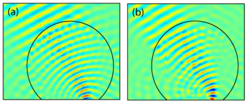
Figure 1 shows the optimized relative permittivity distribution for the flattened lens, the hole distribution computed by the particle interaction approach described above, and the final fabricated lens. Plots of the simulated and measured electric field distributions are shown in Figure 2. The field distribution was measured using a 2D electric field mapping apparatus previously reported [18]. For both the simulations and the experimental measurements, a source was placed at the focal plane of the lens, with a roughly collimated beam expected as the output. In the experimental setup, the source consisted of a dielectric rod waveguide with square cross-section coupled to the focal surface of the lens. Simulations were performed using COMSOL Multiphysics, a commercial finite element solver. The agreement between the simulated and measured field patterns was found to be excellent.
3. Optical Performance Analysis
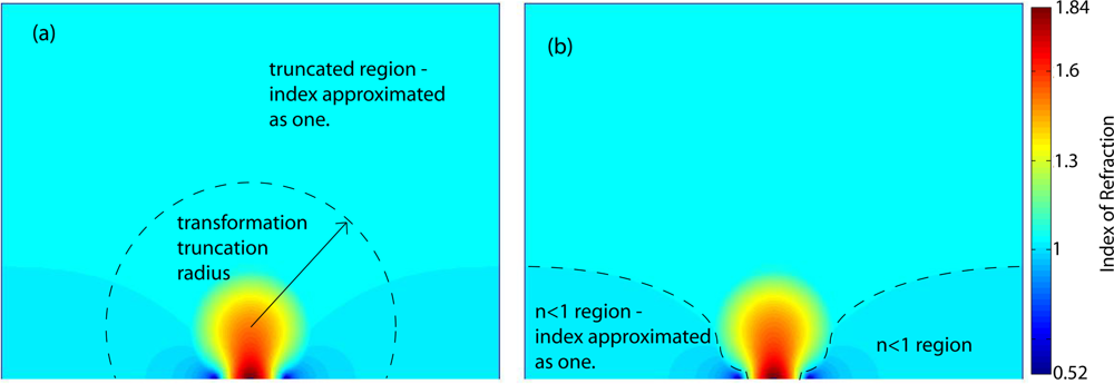
In this implementation of the flattened Luneburg, two approximations of the index distribution prescribed by the transformation were made. Because the transformation ideally extends through all space, the free space index outside the untransformed lens is also modified. In order to perfectly preserve the behavior of the Luneburg, the entire transformation should be implemented, but to make a reasonably sized lens the transformation should be truncated close to the transformed lens’s boundary. The deviation from unity index decreases with distance from the lens, but at some point the transformation must be truncated and the index set to one. Thus the first approximation is to set the transformation index to one beyond some radius, as shown in Figure 3(a). Rays incident from free space outside the transformed region will refract at the boundary, slightly distorting their paths. In addition, they will not be guided by the transformation where it has been truncated. For the lens implemented here, the transformation was truncated at the boundary of the transformed lens.
The second approximation has a slightly more severe effect. For regions at the edges of the flattened region of the lens, the transformation indices take values less than one. To avoid using resonant metamaterials, these indices must be approximated as one, as shown in Figure 3(b). This reduces the aperture of the lens because rays that enter the lens at the edge of the aperture, or rays incident from the side of the lens, must pass through these n < 1 regions and so are not steered correctly when these regions are removed.
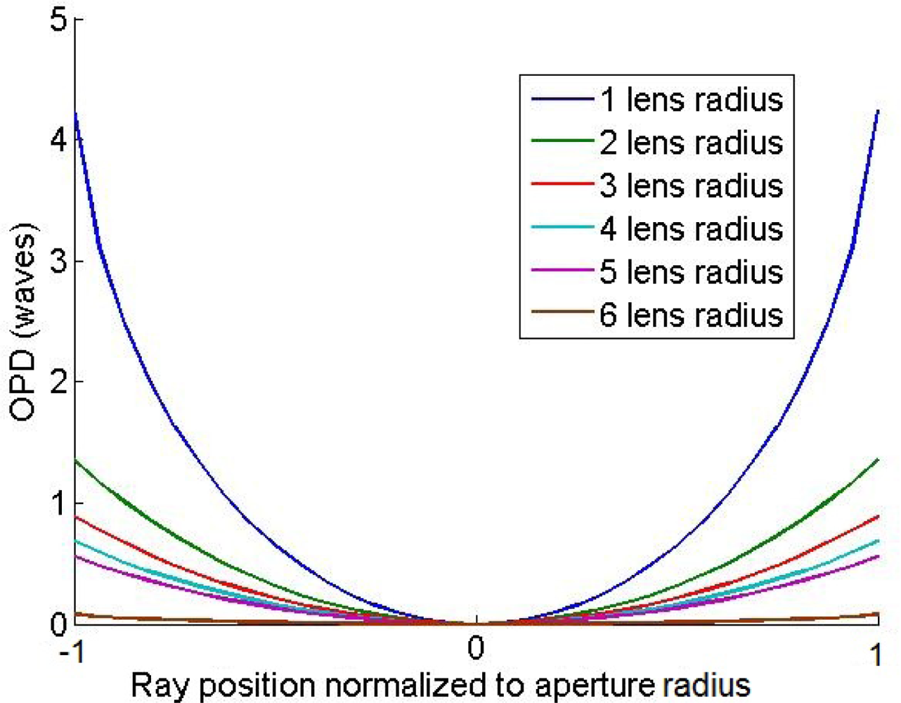
The effect of these approximations can be better quantified by performing ray traces through the transformed lens and calculating the optical path difference (OPD) and spot diagrams. Similar ray tracing analysis has been used to compare three dimensional quasi-conformal transformations, which require anisotropic index of refraction, and their isotropic approximations [10]. To simplify the ray-tracing, a traditional non-refractive Luneburg lens was used for the ray traces. For the un-approximated transformed lens, the OPD is zero for all rays and for all angles of incidence. Truncating the transformation region introduces spherical aberration, a fourth order term in the on-axis OPD, as seen in Figure 4. Fortunately at distances just beyond the lens boundary the transformation index is only approximately 1.01 and falls off rapidly, so the amount of spherical aberration introduced by the truncation is small. The maximum amount of spherical aberration occurs when the transformation is truncated at the boundary of the lens.
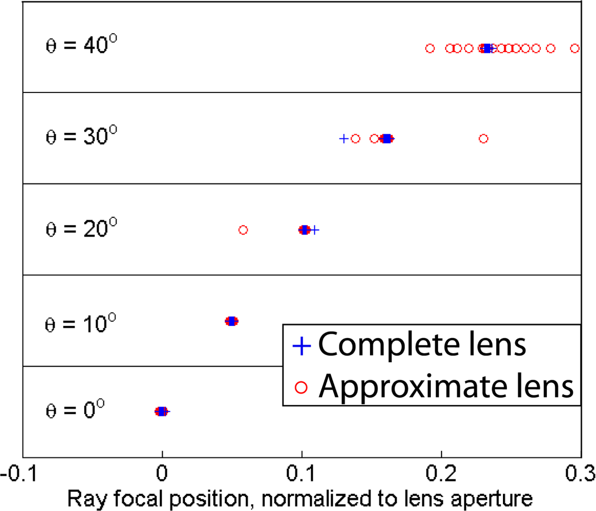
When the n < 1 regions of the lens are set to one, rays that pass near the center of the lens are still focused correctly but rays that pass near the edge of the lens aperture are not, reducing the effective aperture of the lens. For rays near normal incidence this approximation has little effect because the only rays that travel through this n < 1 region are the rays very close to the edge of the lens aperture. This becomes more of a problem for rays incident far off normal because more rays must travel directly trough the n < 1 region outside the lens before entering the lens, as can be seen in Figure 3. The spot diagrams for the un-approximated lens and the n > 1 lens are shown in Figure 5. Beyond a certain angle, the spot diagram rapidly spreads out. This is the angle at which rays begin to pass trough the n < 1 region outside the lens.
In addition to aberrations introduced by these two approximations, distortion aberrations are also present. This is an interesting effect caused by the transformation itself, and indeed is present in the full-transformation lens as well. In order to preserve orthogonality in the quasi-conformal transformation, the x-coordinates are allowed to ‘slip’ on the flattened boundary, i.e., a Neumann boundary condition is applied to this boundary in the numerical calculation of the transformation [9]. This means that line of constant-x are not uniformly spaced across the flattened boundary, resulting in distortion. This distortion aberration is observed in the OPD plots for off-normal incidence rays. However, because the transformation is known, this distortion can be exactly corrected by applying the inverse transformation to the points on the flattened focal boundary.
4. Results and Discussion
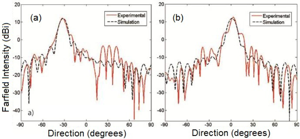
The performance of the lens was quantified by analyzing the far-field patterns of the lens, shown in Figure 6, using a two dimensional Kirchhoff integral. For all incident angles up to the max of ±30°, the experimental lens exhibits a gain of approximately 16 dB and a beam full-width-at-half-max of approximately 8°, comparable to the simulated continuous lens. The disagreement in the side lobes that is seen is due to the inability to achieve permittivities below 1.5 at the lower edges of the lens due to hole percolation. This could be addressed by introducing a lower index host material in these regions.
In conclusion, we designed and fabricated a lens which exhibits focusing over a field of view of ±30° with very little aberration. The design utilizes a refractive Luneburg which has been flattened using a quasi-conformal transformation to produce a flat focusing surface appropriate for planar detector/transmitter arrays. Using the refractive Luneburg as a starting point for our design allowed the lens to be implemented with a semi-crystalline distribution of holes drilled in a dielectric. The design and fabrication approaches are well suited for scaling transformation optical structures to IR and visible wavelengths. The two approximations made in this implementation—the approximation of indices outside the lens and indices less than one as one—have been investigated using ray tracing and were found to introduce only small aberrations.
Acknowledgments
This work was supported through a Multidisciplinary University Research Initiative, sponsored by the Army Research Office (Contract No. W911NF-09-1-0539). N. Kundtz would like to acknowledge the IC postdoctoral fellowship program.
References
- Marchland, EW. Gradient Index Optics; Academic Press: New York, NY, USA, 1978. [Google Scholar]
- Luneburg, R. Mathematical Theory of Optics; Brown University: Providence, RI, USA, 1944. [Google Scholar]
- Ko, H; Stoykovich, M; Song, J; Malyarchuk, V; Choi, W; Yu, CJ; Geddes, J; Xiao, J; Wang, S; Huang, Y; Rogers, J. A hemispherical electronic eye camera based on compressible silicon optoelectronics. Nature 2008, 454, 748–753. [Google Scholar]
- Schurig, D. An aberration-free lens with zero F-number. New J. Phys 2008, 10, 1–11. [Google Scholar]
- Kundtz, N; Smith, DR. Extreme-angle broadband metamaterial lens. Nat. Mater 2009, 9, 129–132. [Google Scholar]
- Pendry, JB; Schurig, D; Smith, DR. Controlling electromagnetic fields. Science 2006, 312, 1780–1782. [Google Scholar]
- Smith, DR; Yaroslav Urzhumov, NBK; Landy, NI. Enhancing imaging systems using transformation optics. Opt. Express 2010, 18, 21238–21251. [Google Scholar]
- Li, J; Pendry, JB. Hiding under the carpet: A new strategy for cloaking. Phys. Rev. Lett 2008, 101, 1–4. [Google Scholar]
- Landy, N; Padilla, W. Guiding light with conformal transformations. Opt. Express 2009, 17, 14872–14879. [Google Scholar]
- Landy, N; Kundtz, N; Smith, DR. Designing three-dimensional transformation optical media using quasiconformal coordinate transformations. Phys. Rev. Lett 2010, 105, 1–4. [Google Scholar]
- Valentine, J; Li, J; Zentgraf, T; Bartal, G; Zhang, X. An optical cloak made of dielectrics. Nat. Mater 2009, 8, 568–571. [Google Scholar]
- Gabriell, L; Cardenas, J; Poitras, C; Lipson, M. Silicon nanostructure cloak operating at optical frequencies. Nat. Photon 2009, 3, 461–463. [Google Scholar]
- Morgan, SP. General solution of the Luneberg lens problem. J. Appl. Phys 1958, 29, 1358–1368. [Google Scholar]
- Luryi, S; Subashiev, AV. Waveguides with uniaxially patterned layers. Proc. SPIE 2006, 6127, 1–15. [Google Scholar]
- Grigoropoulos, N; Young, P. Low Cost Non Radiative Perforated Dielectric Waveguides. Proceedings of 33rd European Microwave Conference, Munich, Germany, 7–9 October 2003; pp. 439–442.
- Xue, L; Fusco, V. 24 GHz automotive radar planar Luneburg lens. IET Microw. Antennas Propag 2007, 1, 624–628. [Google Scholar]
- Hunt, J; Kundtz, N; Landy, N; Smith, DR. Relaxation approach for the generation of inhomogeneous distributions of uniformly sized particles. Appl. Phys. Lett 2010, 97, 1–3. [Google Scholar]
- Justice, B; Mock, J; Guo, L; Degiron, A; Schurig, D; Smith, DR. Spatial mapping of the internal and external electromagnetic fields of negative index metamaterials. Opt. Express 2006, 14, 8694–8705. [Google Scholar]


© 2011 by the authors; licensee MDPI, Basel, Switzerland. This article is an open access article distributed under the terms and conditions of the Creative Commons Attribution license (http://creativecommons.org/licenses/by/3.0/).
Share and Cite
Hunt, J.; Kundtz, N.; Landy, N.; Nguyen, V.; Perram, T.; Starr, A.; Smith, D.R. Broadband Wide Angle Lens Implemented with Dielectric Metamaterials. Sensors 2011, 11, 7982-7991. https://doi.org/10.3390/s110807982
Hunt J, Kundtz N, Landy N, Nguyen V, Perram T, Starr A, Smith DR. Broadband Wide Angle Lens Implemented with Dielectric Metamaterials. Sensors. 2011; 11(8):7982-7991. https://doi.org/10.3390/s110807982
Chicago/Turabian StyleHunt, John, Nathan Kundtz, Nathan Landy, Vinh Nguyen, Tim Perram, Anthony Starr, and David R. Smith. 2011. "Broadband Wide Angle Lens Implemented with Dielectric Metamaterials" Sensors 11, no. 8: 7982-7991. https://doi.org/10.3390/s110807982